Data
Metis data description
Metis can acquire data from both the visible-light (VL) and ultraviolet (UV) channels, independently and simultaneously, and can generate all the following data products.
| VL channel | Polarized-brightness sequences |
|---|---|
| Total-brightness images | |
| Fixed-polarization images | |
| Light curves | |
| UV channel | Analog-mode acquisitions |
| Photon-counting acquisitions | |
| Offset maps | |
| Both | Temporal noise acquisitions |
| Cosmic-ray and SEP log matrices |
Metis data will be processed according to the following processing level definitions:
- Level 0 (L0): uncalibrated data (units of DN) obtained from grouped telemetry packets, that are uncompressed and formatted in standard FITS format. The FITS headers contain only information that is available from the telemetry packet headers.
- Level 1 (L1): uncalibrated data (units of DN). The FITS files contain extra engineering data from housekeeping telemetry packets.
- Level 2 (L2): calibrated data (physical units). Corrections for bias, dark-current, flat-field, and vignetting are applied together with exposure normalization, pointing adjustment, and radiometric calibration. All available orbital and attitude information is used and coordinates are expressed in scientific coordinate systems (WCS).
- Level 3 (L3): science data derived from level-2 data after scientific analysis, e.g., electron-density and solar-wind outflow velocity maps; Carrington maps; filtered images; movies.
Further information on the Metis FITS files structure and processing concepts can be found in the Solar Orbiter/Metis Data Product Description Document or in this presentation.
Polarized-brightness sequences
The VL detector acquires and delivers frames at a constant rate and detector integration time. Each frame is acquired at a different known and configurable polarization angle. The measurement is carried out cycling over a number of specified polarization angles, thus producing an interleaved data stream; this number can assume the values three or four. The on-board data-processing pipeline is capable of executing auxiliary computations and monitoring, i.e., statistics, cosmic-ray (CR) and solar-energetic-particle (SEP) removal, and coronal-mass-ejection (CME) detection.
Eventually, the frames with the same polarization are averaged and compressed in order to deliver to ground a set of polarization images at the specified cadence. This acquisition scheme has a minimum detector integration time of 15 s.
Polarized-brightness sequences will be combined to also provide level-2 polarization data, i.e., Stokes parameters, polarized-brightness and total-brightness images, linear polarization degree and angle maps.
Total-brightness images
The VL detector acquires and delivers frames at constant rate and detector integration time. The number of polarization angles can assume only the value of two. All frames are acquired by switching the polarization in the middle of the detector integration. The on-board data processing pipeline is capable of executing the auxiliary computations and monitoring described above.
Eventually, the frames are averaged and compressed in order to deliver to ground a single image at the specified cadence. This acquisition scheme has the limitation of a minimum detector integration time of 20 s.
Fixed-polarization images
The VL detector acquires frames at a given detector integration time and delivers them at constant rate. This acquisition scheme was created in order to perform acquisitions at a high rate. All frames are acquired by keeping the polarization angle at the same fixed value. All auxiliary computation and monitoring algorithms are disabled.
Eventually, the individual frames are compressed and delivered to ground. This acquisition scheme has the limitation of a minimum detector integration time of 1 s and of a maximum number of 64 frames. At 1 s integration time and for 64 frames, the total acquisition time is about 11 minutes, including the processing time.
Light curves
During the acqusition of a polarized-brightness sequence, the VL channel can also provide the light curves, that is, eight temporal series of mean brightness computed averaging the counts detected in the pixels within eight radial sectors of the Metis field of view. Whenever the production of the light curves is enabled, these data products are downloaded as well, together with the polarized-brightness sequence.
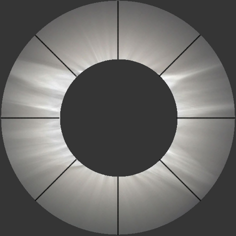
Metis field of view, with the eight sectors used for the computation of the light curves
UV analog-mode acquisitions
The frames acquired by the UV detector at constant integration time, are averaged in a two-step process. The first is performed in hardware (pre-sum) and the second via software (coadding). The on-board data processing pipeline is capable of executing the auxiliary computations and monitoring, i.e., statistics and CR/SEP removal.
Eventually, the resulting image is compressed and delivered to ground. This acquisition scheme has the limitation of a minimum detector integration time of 1 s.
UV photon-counting acquisitions
In this case, the APS is operated continuously, nominally at 97 ms integration time, i.e., the maximum frame rate allowed in order to avoid overlapping of the charge spots generated by each primary photon impinging on the detector.
The output data are serially acquired by the photon-counting unit (PCU) so as to generate a 3×3 pixel event window that dynamically sweeps the APS matrix. Each window is analyzed, searching for the presence of events whose charge content lies within proper limits and satisfies a given set of morphological rules. The PCU algorithm performs three tasks: offset correction, photon detection, and photon-list generation. The PCU will determine the centroid coordinates of the identified events and subsequently send a packet containing coordinate pairs and collected photon-charge information to the Metis Processing & Power Unit (MPPU).
While in photon-counting mode, the UV data can be delivered in three different output formats:
- Photon list format, if the count rate is below a parameterized threshold;
- Accumulation, when the count rate is higher than the same parameterized threshold; in this mode the MPPU does not generate the list of events, but it collects the data in a 1024×1024 matrix;
- Test mode, which provides the value of each pixel in a 3×3 window centered on detected photon events, is used to perform diagnostic and test procedures able to verify the status of the photon-counting/photon-list operation mode and the UV detector efficiency/functionality.
Offset maps
The purpose of this acquisition is to correct for possible offset variations on the APS pixel-electronic chains during the mission. A set of N (N = 8, 16, 32, 64, 128) frames is acquired, with the minimum exposure time (97 ms) and with the MCP intensifier switched off. The frames are then averaged with a pixel-by-pixel arithmetic mean. The averaged frame is sent to ground and at the same time stored on-board, in order to be used in the photon-counting acquisition as offset correction matrix. The same map is stored in a separate memory slot as a backup.
Temporal noise acquisitions
This acquisition is common to both channels. The detector acquires a given number of frames at a given detector integration time and computes the mean and standard deviation for each sensor pixel. For the VL channel, all frames are acquired by keeping the polarization angle at the same fixed value. The purpose of this acquisition is to periodically monitor the detector performance. The two frames, one with the mean and the other with the standard deviation, are compressed and delivered to ground. For this acquisition, no auxiliary computational and monitoring process is active.
Cosmic ray and SEP log matrices
This data product is generated by the CR/SEP correction algorithm. It consists in a map of the pixels affected by CR/SEP hits that were corrected in the associated primary product.